HVAC DESIGN BASICS
Duct System: Follow Manual D Procedures
Proper duct design is critical for any home for the comfort system(s) to deliver promised comfort levels.

Step One: The process begins with a room-by-room Manual J heat loss/gain calculation. This calculation is the staging point for all aspects of the heating and air conditioning system which will follow. This calculation will determine the air flow requirements for each room, supply register, and return grille.
Step Two: The designer determines from the calculation, the best equipment to meet the system's, or home's, requirements. Here he should follow ACCA's Manual S: Residential Equipment Selection guide. This step determines the the specific blower performance, which then becomes critical in the duct design / sizing process.
Step Three:
A rough sketch
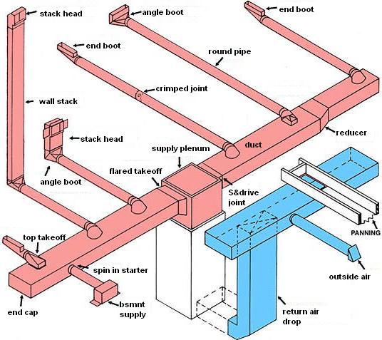
of the home's preferred air distribution system is drawn showing equipment placement, register and return locations, air flow requirements for each room, each supply register and return grille, and the location and lengths of ductwork to tie it all together. More than 1 sketch may be necessary to determine the best duct layout based on the architectural layout and structural members of the home.

Step Four: Now ductwork sizing begins. ACCA's Manual D procedures size the ductwork accounting for blower performance, room-by-room cfm needs for both cooling and heating, distance of ducting to each register or return, all ductwork fittings in the system, type of ducting material planned (sheet metal, flex, or duct board), and any other restrictions in the duct system.
Perfect-Home-Hvac-Design
can provide Manual J, Manual D, Manual S, and simplified Duct Design Services for minimal cost. All of the above steps are an integral production of your Wrightsoft based hvac system design prepared for you by Perfect-Home-Hvac-Design.
Plus you will have all the reports and diagrams for your local friendly building inspector.
From here you can take your duct design to your neighborhood hvac fabricator, and move on to step 5.
It is important to note here that not all ducting materials are created equal. A 6" round flexible duct does not flow air as well as a 6" round galvanized duct does. An 8"x12" ductboard trunk does not move as much air as an 8"x12" sheet metal duct does.
Step Five: Fabrication. This is where the ideas on paper begin to take shape. A fabrication list is created and shop personnel build the ducting and fittings. Poorly designed, fabricated, or badly sealed ductwork reduces the system's efficiency by as much as 40%, costing the homeowner money and creating a drafty, uncomfortable home. Well sealed ducting begins in the shop, and continues through the installation. Rectangular tees, ells, take-offs, reducers should be rounded for best air flow. Square fittings of any sort in a duct system inhibit air flow.

Step Six: The installation. This is where a perfect duct design can be completely made or broken. Rectangular tees, ells, take-offs, reducers should be rounded for best air flow. Square or right angle fittings of any sort in a duct system inhibit air flow. A square tee or ell can add 100' of equivalent length to the duct system. All fittings in the duct system and their equivalent length should have been accounted for during the manual D procedure.
Special attention should be taken here to the joints in the duct system. All joints in the ductwork should be sealed with mastic duct sealant or an approved duct tape. This will ensure that all air is delivered to the conditioned living space. If joints are badly sealed the overall system will operate at a lower efficiency and needlessly waste energy.
Sometimes the duct system design is undertaken by the architect in a residential application. More often than not, this design is meant to show preferred duct location for fir-downs only. Usually any duct sizing must still be determined by undertaking the above procedures. The opposite is true for commercial projects. Often a commercial project has been fully designed by a mechanical engineer and his designs must be followed.
The
Air Conditioning Contractors of America
(ACCA) Manual J, Manual D, and Manual S are invaluable guides for designing a well performing duct system. Following these guidelines, plus hiring an hvac contractor that will follow good installation practices will ensure a quality end product.
Other organizations setting the standards for Hvac installations and ductwork specifications are ASHRAE (
American Society of Heating, Refrigerating, and Air Conditioning Engineers
) and SMACNA (
Sheet Metal and Air Conditioning Contractors' National Association
).

Duct Design Related Pages
HVAC FOR BEGINNERS: The Residential Forced Air Duct System: Trunk and Branch Duct Systems
HVAC FOR BEGINNERS: A Guide to Good Ducting Practices: Plenums and Return Air Drops
Basic How-To Duct Installation
Duct Fittings: Ells, Tees, and Reducers
More Ductwork Transitions: Side Take-offs and Vertical Ells
Multiple Fittings in a Duct System
Residential Hvac Duct Drawings
Article by: Geoffrey R. Stoddard, Hvac Designer / Detroit, Michigan
Leave Duct Design and Return to HOME
Please feel free to link to this page from your website. This page's URL is: http://www.perfect-home-hvac-design.com/duct-design.html


